Network
Table of contents
Displays a network.
Requires a loaded network file.
Network
Using the settings, it is possible to offset links either to the left or the right such that the links in opposing directions are not drawn on top of each other.
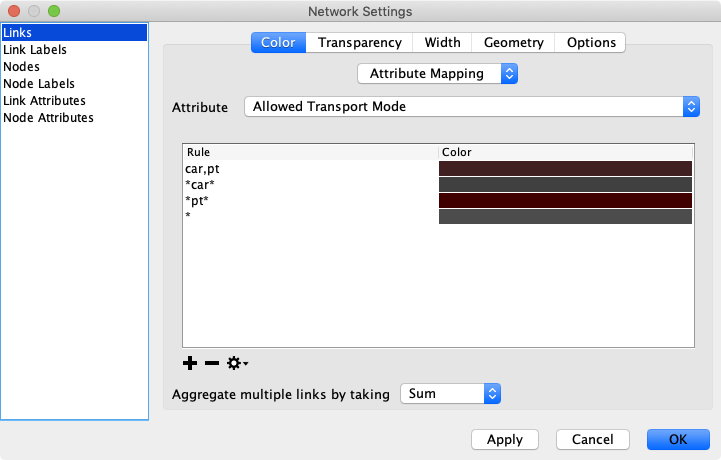
The colors and width of links can be modified by clicking on the gearwheel (options) icon. It is possible to assign different colors to links with different allowed modes, different number of lanes, different capacity and other attributes. Also, one can display links with different width depending on links’ attributes (allowed modes, number of lanes, and others). When setting the values based on allowed modes and a link should match multiple modes, separate the various modes with a comma. If a link should match having at least one specific mode, enclose the mode with asterisks (*). The color of a link is determined by the first (top-most) mode-description that matches the links’ transport modes.
The list of attributes available to set the appearance of links in the network can be extended with additional attributes loaded from a variety of files. Supported files are MATSim’s Object Attributes saved as XML file, tab-separated text files, or CSV files.
Detailed Link Geometry
By default, all links are drawn as straight lines between from- and to-node, as MATSim does not support more detailed geometries per link. But Via does! Open the network’s settings dialog and switch to Geometry in the Links-section. There, you have the option to load a file containing detailed link geometries. The link-geometry is described as a series of coordinates that are placed between the from- and the to-node of the link.

The link geometries for each link must be encoded as a String, but many different formats are supported: Whether with round brackets, square brackets, with comma or semicolon in between, it all works. In addition, WKT linestrings are supported as well.
LINK_ID     GEOMETRY
123         (x1,y1),(x2,y2),(x3,y3)
124         (x1,y1)(x2,y2)(x3,y3)
125         [x1,y1],[x2,y2],[x3,y3]
126         [[x1,y1],[x2,y2],[x3,y3]]
127         x1,y1; x2,y2; x3,y3
128         LINESTRING (x1 y1, x2 y2, x3 y3)
The coordinates of the from- and to-node do not have to be included in the list, as they are known anyway.
After loading the link geometries, links are drawn in more detail as shown below (left: default visualization, right: with link geometries): 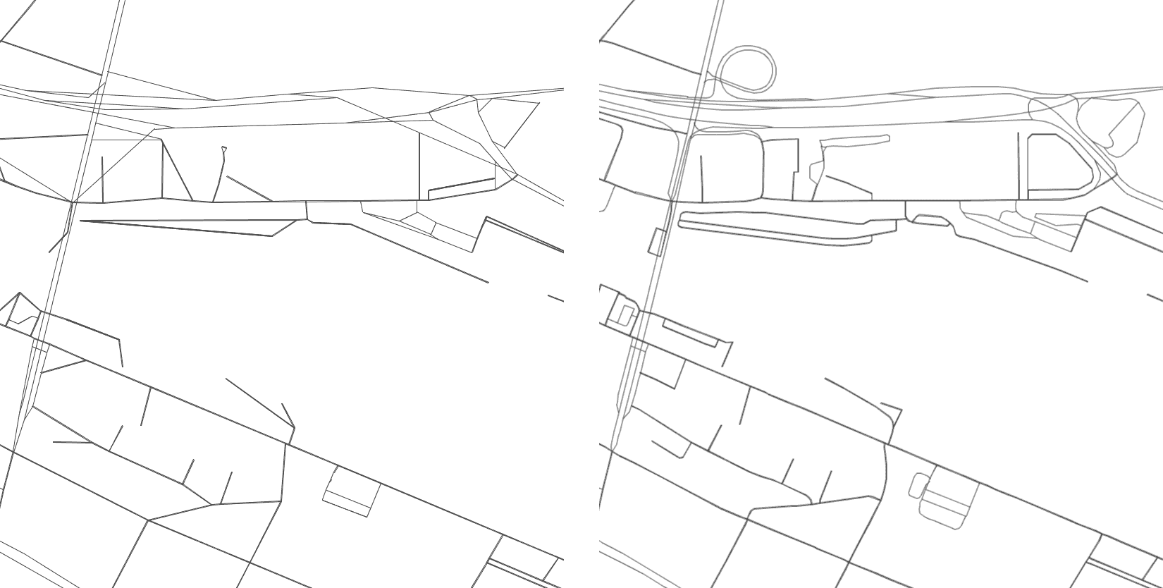
The provided example data for Via includes corresponding example files.